VTKpytools/Barfiletools
barfiletools is a module within the VTKpytools package containing functions for converting *bar files (velbar, stsbar, etc.) into VTK files and for post-processing those VTK files.
As a reminder, all vtkpytools functions and classes have inline documentation via docstrings. API documentation via Sphinx maybe implemented eventually...
Contents
Overview of Post-Processing *bar Files
- Create "blank" MultiBlock VTK (VTM,
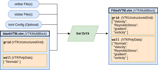
*.vtm) file using custom Python script - Load *bar file data onto blank VTM file using bar2vtk CLI program
- Read the "loaded" VTM file and post-process
The first step only has to be performed once per mesh. The second has to be completed for every timestep to be post-processed.
Examples of each of the three processes listed above can be found in the examples directory of the vtkpytools repository.
VTM File Format
The blank VTM file simply holds the coordinate, connectivity, and geometry information for the domain. Data is then loaded onto these points afterwards.
To allow the tools to be consistent regardless of mesh or geometry, the blank VTM files must have a specified format. It should contain two blocks named grid and wall:
-
grid - A VTK Unstructured Grid of the 2D spanwise mesh and (after data has been loaded onto the VTM file) the data associated with each node
-
wall - A VTK PolyData of the line that defines the wall of the domain. It is a subset of the connectivity and vertices of
grid
For a blank VTM file, grid should have no arrays loaded onto it, and wall should have an array named Normals that contains unit vectors normal to the wall.
Creating Blank VTM File
The process of creating the blank VTM file is:
- Load 2D mesh data
- Specifically, the coordinate and connectivity information of the spanwise mesh. Note that the connectivity array should be indexed at 0 (ie. the first node should be zero).
- If you don't have the connectivity of the 2D mesh, see Create 2D Mesh Connectivity to generate it.
- Generate
grid- Using
vpt.form2DGrid()with the coordinate and connectivity information
- Using
- Extract edges of
grid- Using the
extract_feature_edgesmethod provided by pyvista,
- Using the
- Compute normal vectors of the feature edges
- Using
vpt.computeEdgeNormals()
- Using
- Extract the wall cells from the feature edges
- The most straight forward way to do this is by doing boolean selections based on the wall normal components
- (Optional) Order wall points
- By default, they are not in order of the line. Done using
vpt.unstructuredToPoly()andvpt.orderPolyDataLine()
- By default, they are not in order of the line. Done using
- Save
gridandwallto MultiBlock object
An example script of doing this process is in makeVTM.py in the example directory of the repository.
Once you've saved the VTM file, I suggest you open the file in ParaView to check that it worked well. Specifically, check to make sure that wall was extracted correctly. Using ParaView's "Extract Block" filter may be useful for this task.
Load *bar File Data
Now that you have a "blank" VTM file, you can add *bar file data onto it using bar2vtk, a CLI program. You can find documentation for it by running bar2vtk --help or looking at the Bar2vtk wiki page. It supports:
- Creating timestep windows
- Loading Binary forms of *bar files
- Custom file names/paths to data
This process will create "Pressure", "Velocity", and "ReynoldsStress" quantities in both grid and wall objects. Note that the quantity names are from Appendix A of the CGNS standard.
An example script demonstrating the shell commands for running bar2vtk is in runbar2vtk.sh in the example directory of the repository.
Post-Process "Loaded" VTM File
After the *bar data has been loaded, the file maybe viewed in ParaView for standard visualization. Alternatively (or rather in tandem), you can post-process in Python using a combination of pyvista and vtkpytools. Things you can do are:
- Generate profiles from walls
- Compute C_f (using
vpt.calCf()), T_w, or simply wall-shear velocity gradient (usingvpt.calcWallShearGradient()) - Compute new quantities and save them to a new VTM file
Much of this is a function of using pyvista as the primary interface for VTK, so I'd recommend checking out pyvista's documentation, specifically the section going over attributes (as this is most relevant to "data extraction" post-processing).

